Smart Home Assembly Tutorial
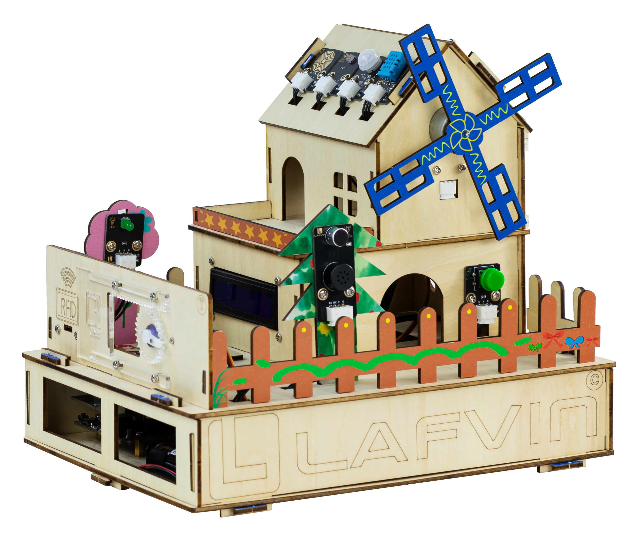
(Design sketch of smart house installation)
Installation video tutorial
Wiring
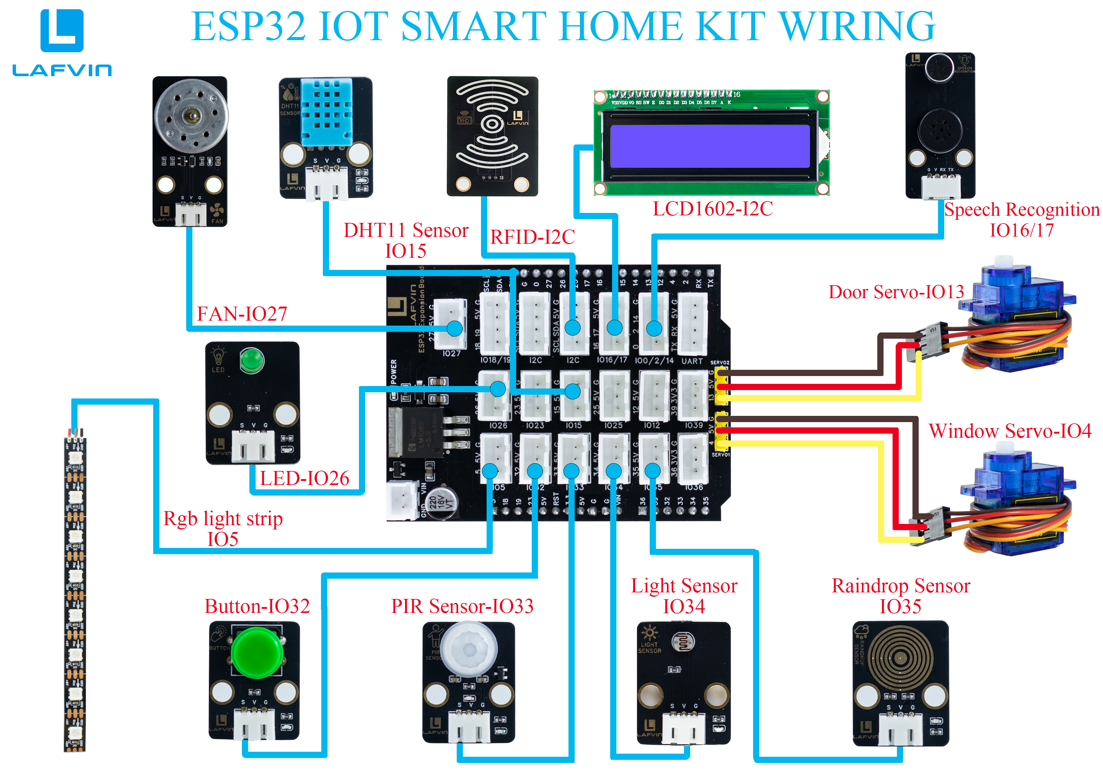
Component |
ESP32 Pin |
|---|---|
Window Servo |
4 |
Door Servo |
13 |
Fan |
27 |
PIR Sensor |
33 |
LED |
26 |
Light Sensor |
34 |
Button |
32 |
DHT11 Sensor |
15 |
Raindrop Sensor |
35 |
Speech Recognition |
16, 17 |
RFID |
I2C-SCL, SDA |
LCD1602 |
I2C-SCL, SDA |
RGB Light Strip |
5 |
With the exception of the servos, all sensors and components in the system utilize standard XH2.54 (3/4-pin) connectors with reverse polarity protection, ensuring plug-and-play operation without requiring polarity identification.
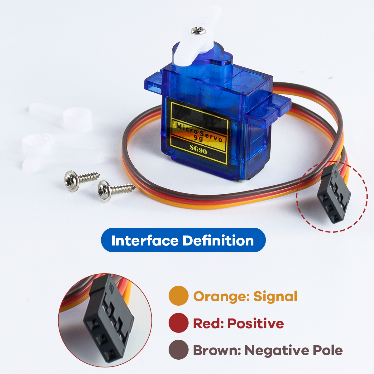
When connecting the servos, please follow the cable colors shown in the following diagram.
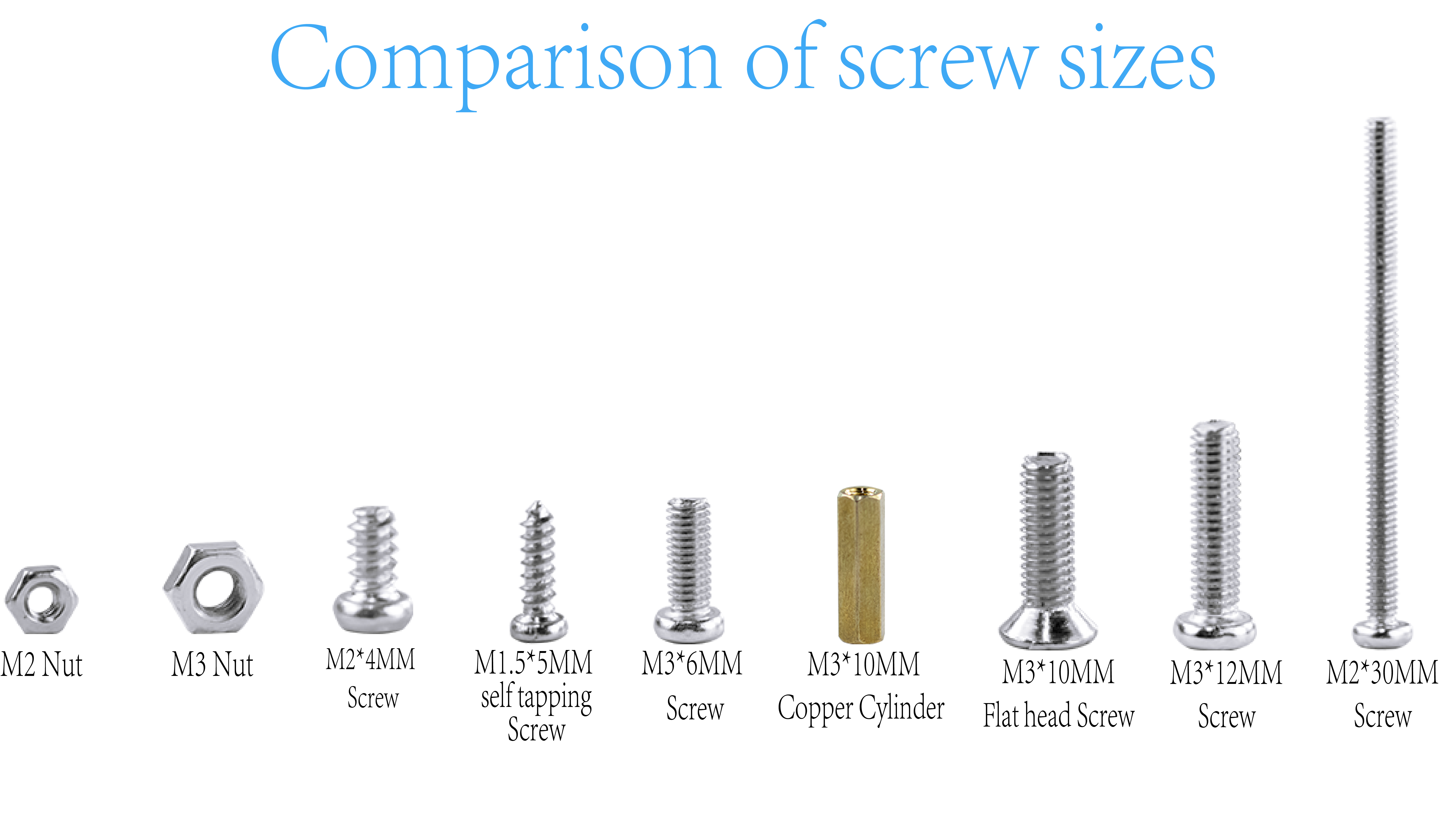
Screw size comparison
This product requires several different screw types during installation. Before installation, please verify each screw type and follow the instructions in this tutorial to use the specified screw type.
Mixing or substituting screw types is strictly prohibited. This may cause installation failure or damage to the product due to screw mismatches. If you are unable to identify the screw type, please discontinue operation and refer to the accessories list or contact customer service for confirmation.
Now, please follow the steps in this tutorial and let’s start installing the “Smart-Home”.
1.Installation of base part
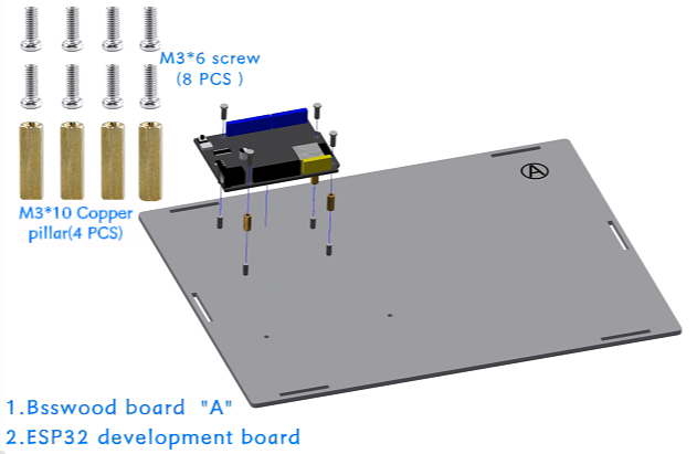
Step 1: Install the ESP32 development board
Parts list: Basswood board with “A”、 ESP32 development board、 M3*6mm screw (8 PCS)、 M3*10mm copper pillar (4 PCS).
The installation is shown in the following figure:
Precautions
First, insert the screws through the underside of the basswood board numbered “A,” then place the copper standoffs and tighten them. Next, place the ESP32 development board and tighten the screws to secure it.
The serial numbers on the basswood boards are used only to distinguish one board from another. In the tutorial examples, the serial numbers face outward for ease of illustration, but they should face inward during installation. This principle should also be followed for subsequent basswood installations.
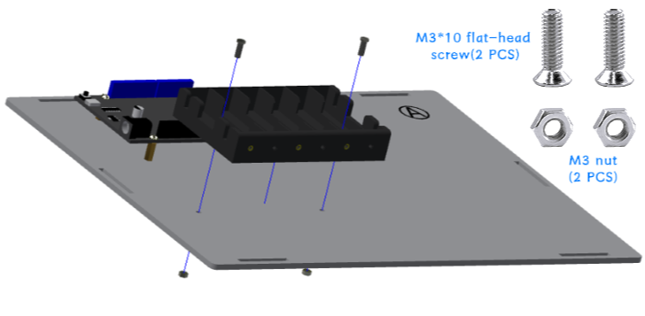
Step 2: Install the battery box
Parts list: battery box、 M3*10mm flat head screw (2 PCS)、 M3 nut (2 PCS).
The installation is shown in the following figure:
Precautions
When securing the battery compartment, use flat-head screws. If you use round-head screws, the screws will protrude and press against the battery, preventing it from being installed properly.
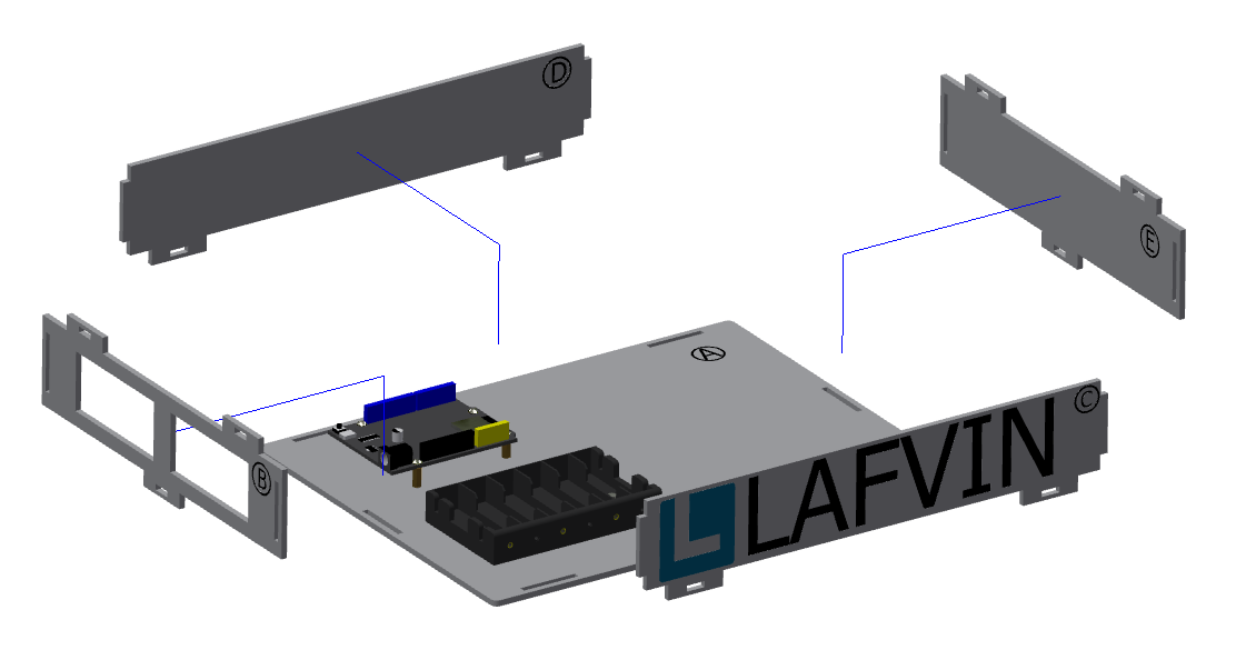
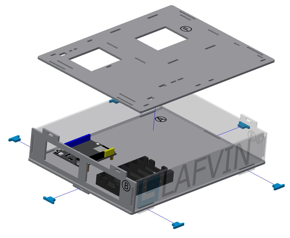
Step 3: Install the base
Parts list: Basswood boards with “B, C, D, E, F”、 blue latch (6 PCS).
The installation is shown in the following figure:
Precautions
The order in which basswood boards with “B, C, D, E” can be installed is not restricted, but basswood board “F” must be installed after them.
In this step, only the six bottom latches need to be installed. The latches connected to the basswood board “F” do not need to be installed yet.
The effect of the base installation is shown in the figure:
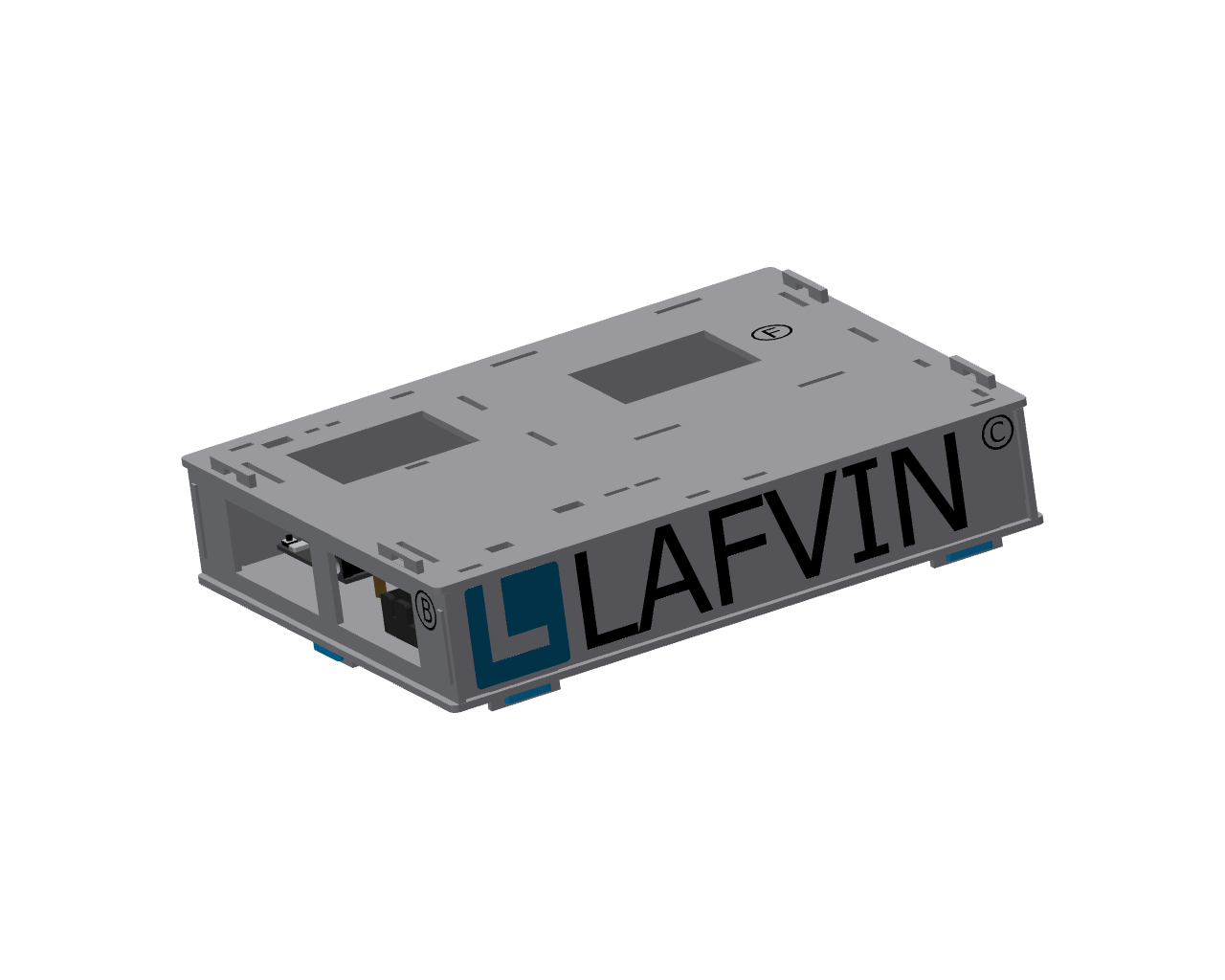
2.Installation of the first floor
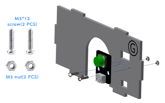
Step 1: Install the button module
Parts list: Basswood board with “G”、 button module、 M3*12mm screw (2 PCS)、 M3 nut (2 PCS).
The installation is shown in the following figure:
Step 2: Install LCD screen
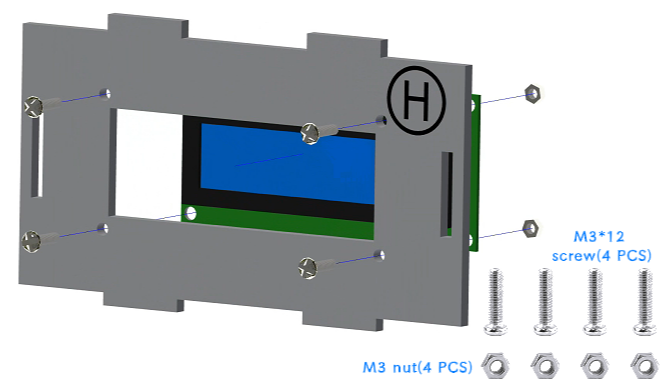
Parts list: Basswood board with “H”、 LCD screen、 M3*12mm screw (4 PCS)、 M3 nut (4 PCS).
The installation is shown in the following figure:
Precautions
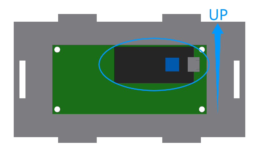
When installing the screen, please make sure that the black panel with the socket is facing upwards to prevent the screen from being displayed upside down due to incorrect installation direction.
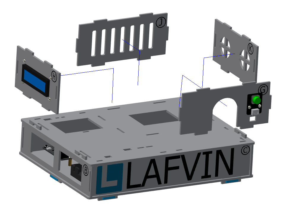
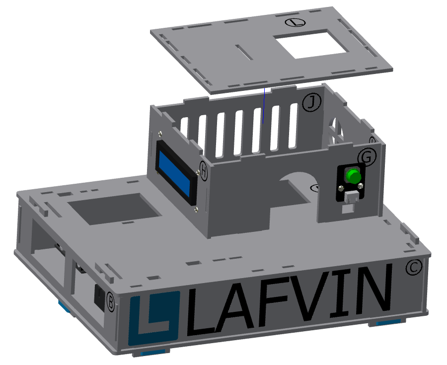
Step 3: First floor assembly
Parts list: Basswood boards with “J, K, L”, and “G, H” with screen and buttons installed.
The installation is shown in the following figure:
Precautions
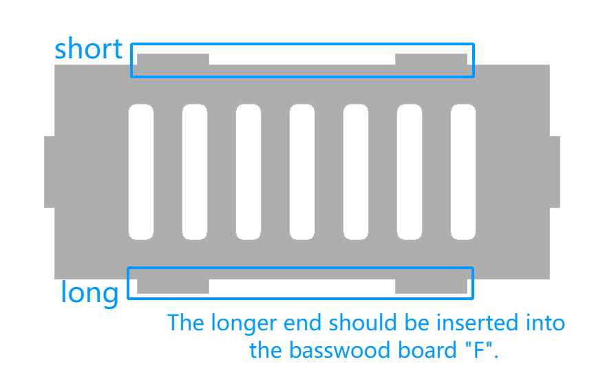
Basswood boards with “G, H, J, K” have different protrusion lengths at the top and bottom. To ensure a secure fit, the longer protruding end should be inserted into the “F” board.
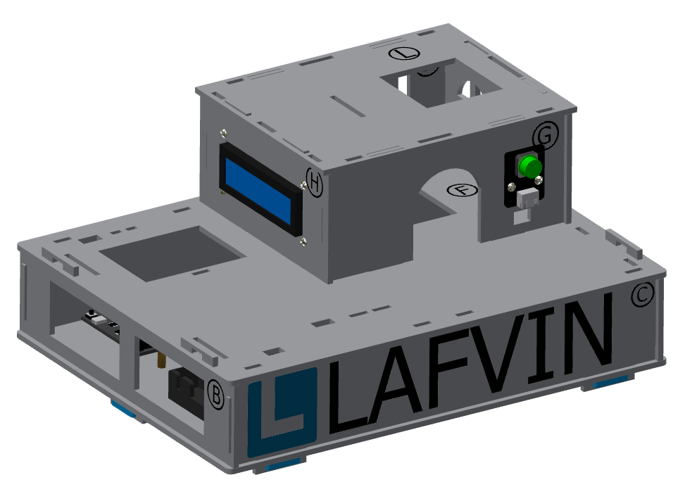
The effect of the first floor installation of the cabin is shown in the figure:
3.Installation of the second floor
Step 1: Install window
Step 1-1: Install of gear and swing arm
Parts list: acrylic gear、 servo bag (one-way swing arm)、 M1.5*5mm self-tapping screw (1 PCS).
The installation is shown in the following figure:
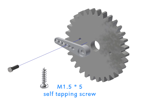
Precautions
Align the small hole of the gear (either left or right) with the third small hole of the swing arm, then install it and tighten the screws.
The gear installation method in this step is the same as the subsequent gate control gear installation steps and parts used, so you can complete the installation in this step.
Step 1-2: Install the window servo on the basswood board
Parts list: Basswood board with “P”、 servo bag (servo)、 M2*30mm screw (2 PCS)、 M2 nut (2 PCS).
The installation is shown in the following figure:
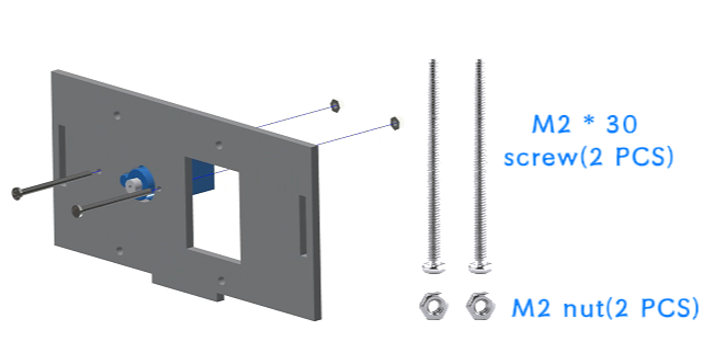
Step 1-3: Install the window gear and acrylic plate onto the basswood board
Parts list: Basswood board with “P”、 window acrylic driver board (shorter acrylic)、 assembled gear、 servo package (shortest screw - M2*4mm)、 M3*12mm screw (4 PCS)、 M3 nut (4 PCS)、Gasket (4 PCS).
The installation is shown in the following figure:
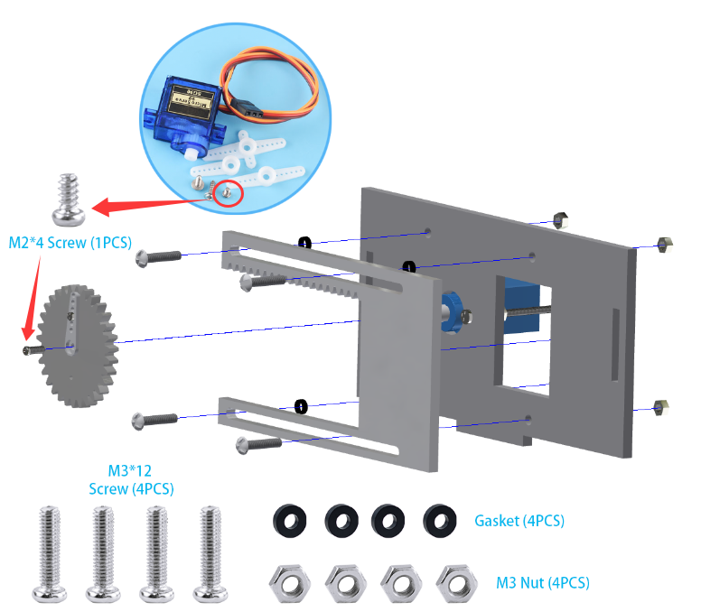
Precautions
There is a film on both sides of the acrylic, please tear it off before installation.
When installing the acrylic window drive plate to the basswood board, the fixing screws do not need to be tightened too much, and appropriate margin should be left to ensure smooth sliding of the window.
The window’s acrylic drive plate should be installed with the rack facing upwards.
Window installation completed effect picture:
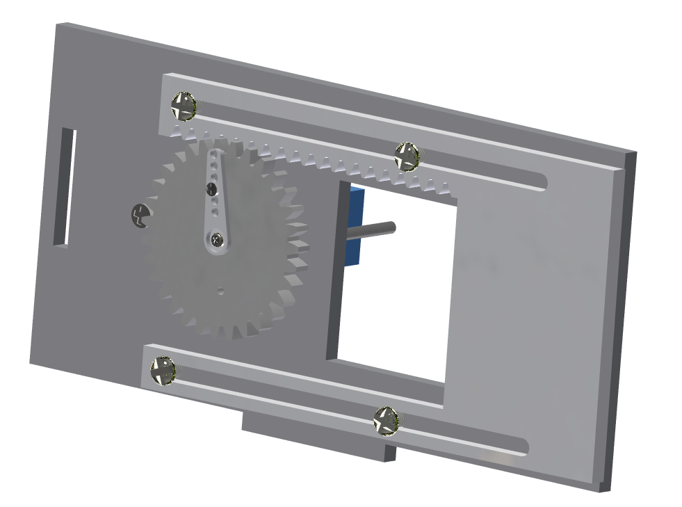
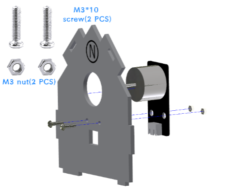
Step 2: Install of the Motor Fan
Parts list: Basswood board with “N”、 motor fan module、 M3*12mm screw (2 PCS)、 M3 nut (2 PCS).
Window installation completed effect picture:
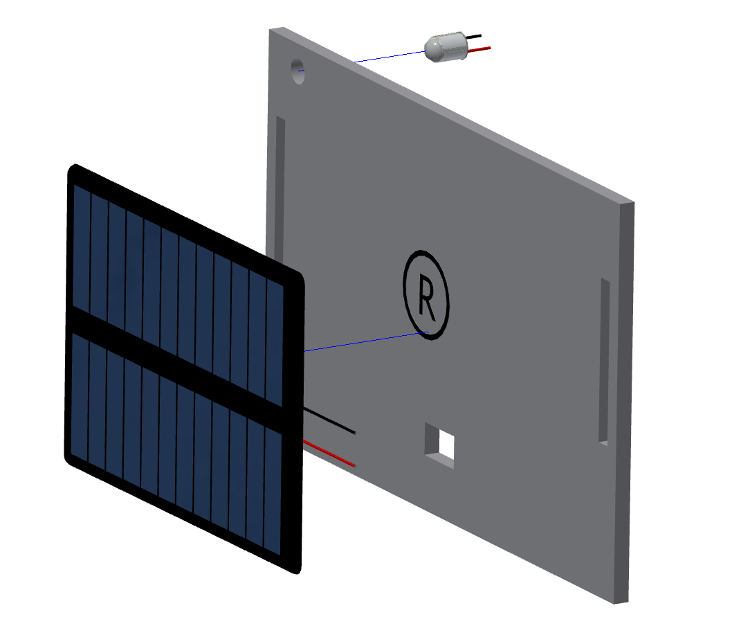
Step 3: Install the Solar Charging Panel
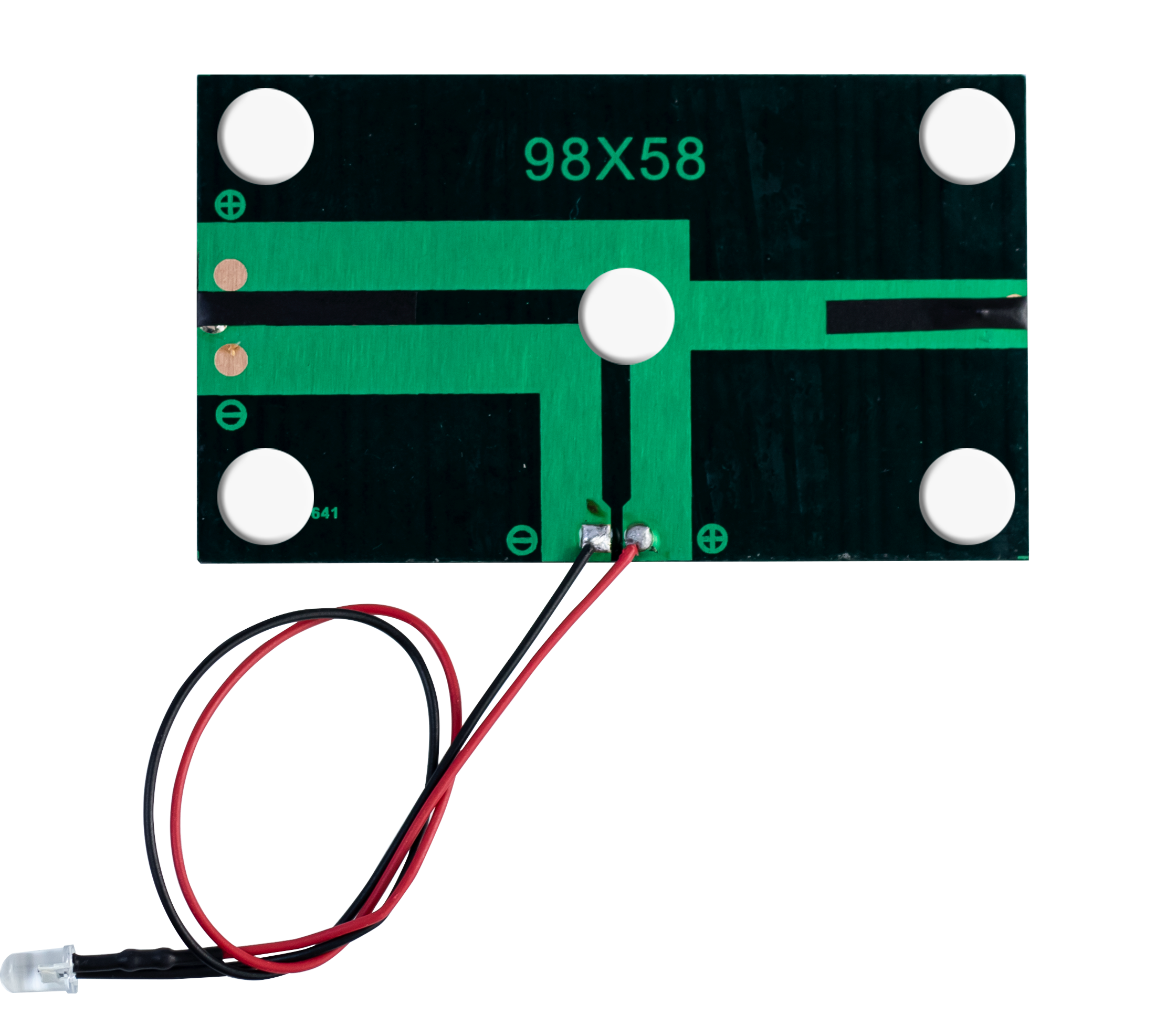
Parts list: Basswood board with “R”、 solar charging panel、 solar charging indicator light、 glue.
The installation is shown in the following figure:
Precautions
The back of the solar panel is fixed to the wooden board with glue. It is more secure if it is glued in the position shown in the picture above.
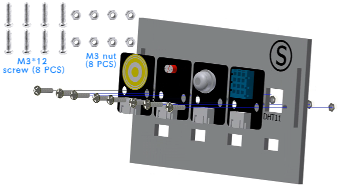
Step 4: Install of the Sensor Module
Parts list: Basswood board with “S”、 DHT11 temperature and humidity sensor、 human infrared sensor、 light-sensitive brightness sensor、 raindrop sensor、 M3*12mm screw (8 PCS)、 M3 nut (8 PCS).
The installation is shown in the following figure:
Precautions
Please fix the sensor in the recommended position according to the text marked on the basswood to ensure a stable and balanced installation.
Step 5: Second floor assembly
Parts list: Basswood boards with “M、 Q”, and “N、 P” basswood boards with components installed.
The installation is shown in the following figure:
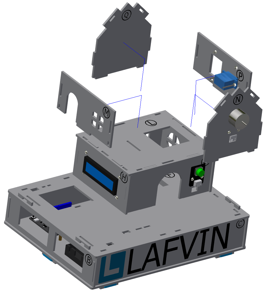
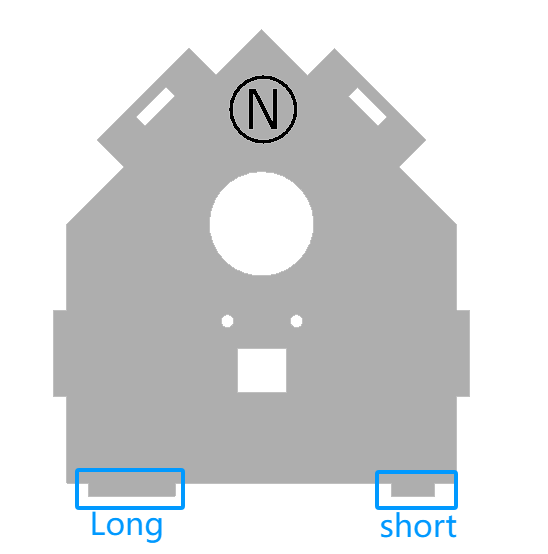
Precautions
The lengths of the protrusions on the left and right sides of the lower ends of the basswood boards with “N, Q” are different. Please carefully distinguish the directions before installing to ensure a stable structure.
Step 6: Install roof
Parts List: “S、 R” basswood board with components installed.
The installation is shown in the following figure:
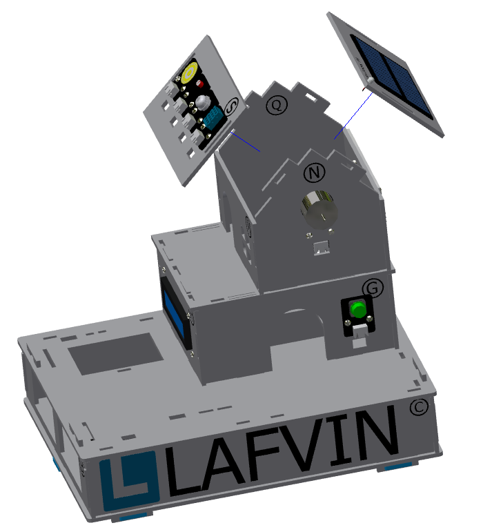
Step 7: Install of the Second Fence
Parts List: Brown basswood fence planks (shorter, 3 PCS).
The installation is shown in the following figure:
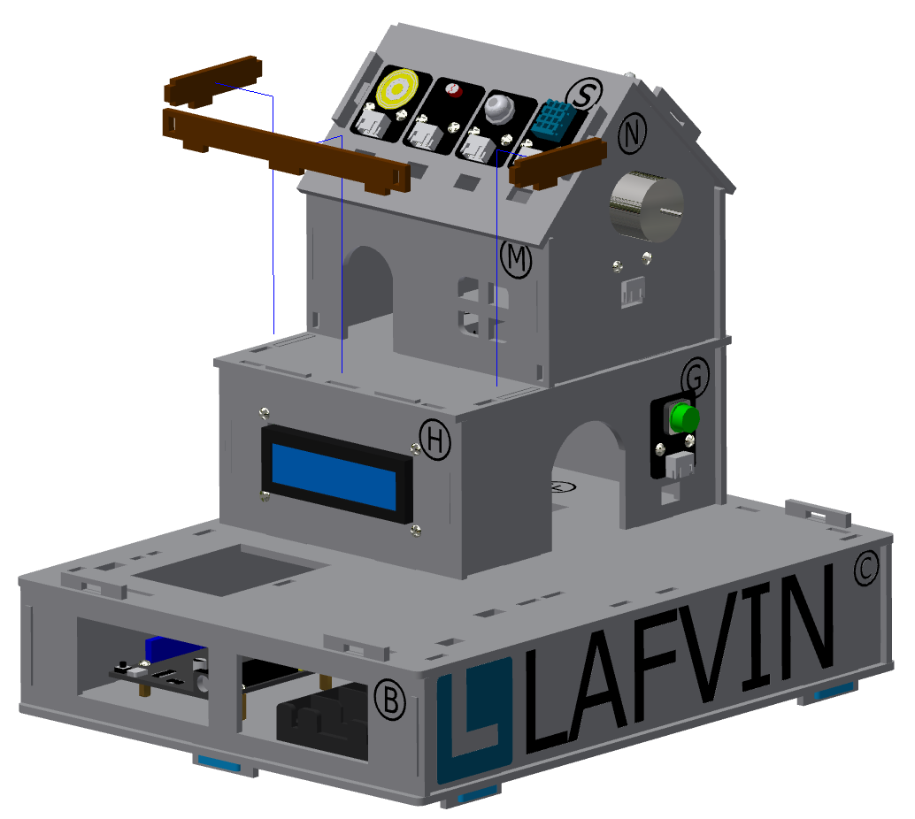
The effect picture of the second floor of the cabin after installation:
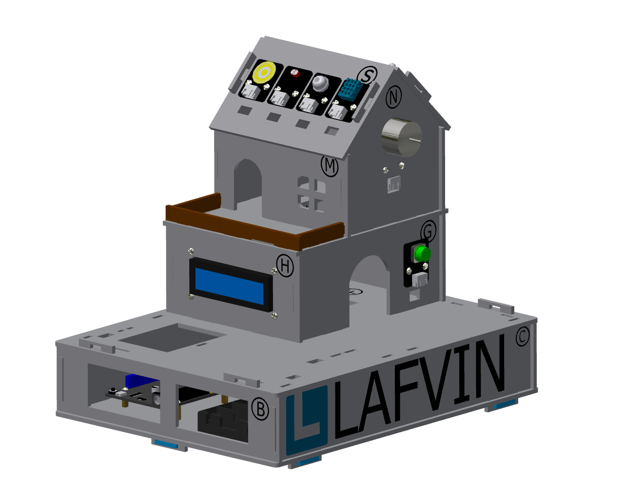
4.Installation of the garden
Step 1: Install of the gate
Step 1-1: Install of gear and swing arm
Parts list: acrylic gear、 servo bag (one-way swing arm)、 M1.5*5mm self-tapping screw (1 PCS).
The installation is shown in the following figure:
Precautions
Align the small hole of the gear (either left or right) with the third small hole of the swing arm, then install it and tighten the screws.
The gear installation method here is the same as the window control gear installation steps and parts. If the previous installation has been completed, this step can be ignored.
Step 1-2: Install the gate servo on the basswood board
Parts list: Basswood board with “T”、 servo bag (servo)、 M2*30mm screw (2 PCS)、 M2 nut (2 PCS).
The installation is shown in the following figure:
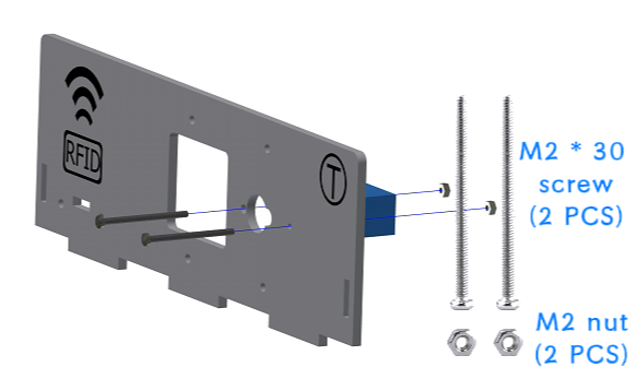
Step 1-3: Install the gate gear and acrylic plate onto the basswood board
Parts list: Basswood board with “T”、 gate acrylic driver board (shorter acrylic)、 assembled gear、 servo package (shortest screw - M2*4mm)、 M3*12mm screw (4 PCS)、 M3 nut (4 PCS)、Gasket (4 PCS).
The installation is shown in the following figure:
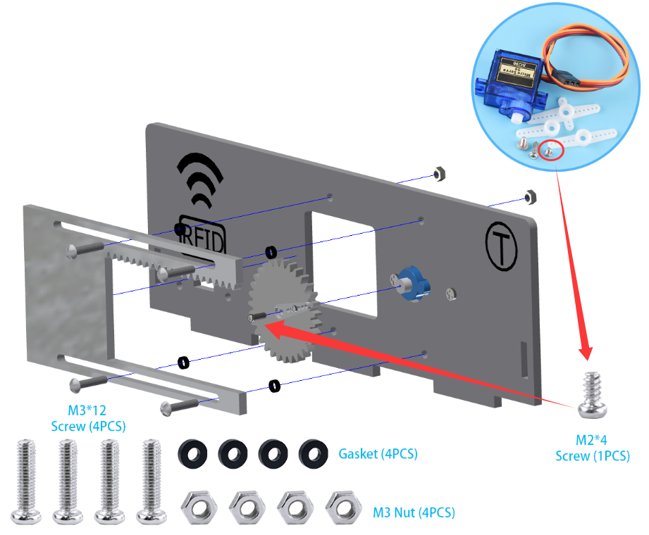
Precautions
There is a film on both sides of the acrylic, please tear it off before installation.
When installing the acrylic gate drive plate to the basswood board, the fixing screws do not need to be tightened too much, and appropriate margin should be left to ensure smooth sliding of the window.
The gate’s acrylic drive plate should be installed with the rack facing upwards.
Step 1-4: Install of RFID sensor module
Parts list: Acrylic door drive board and basswood board “T” with servo installed、 RFID sensor module、 M3*12mm screw (2 PCS)、 M3 nut (2 PCS).
The installation is shown in the following figure:
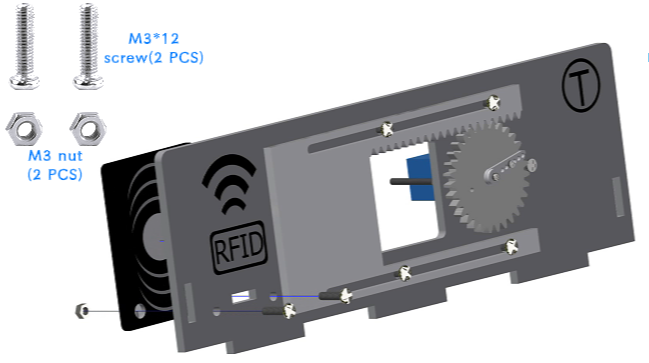
The effect picture of the gate installation is completed:
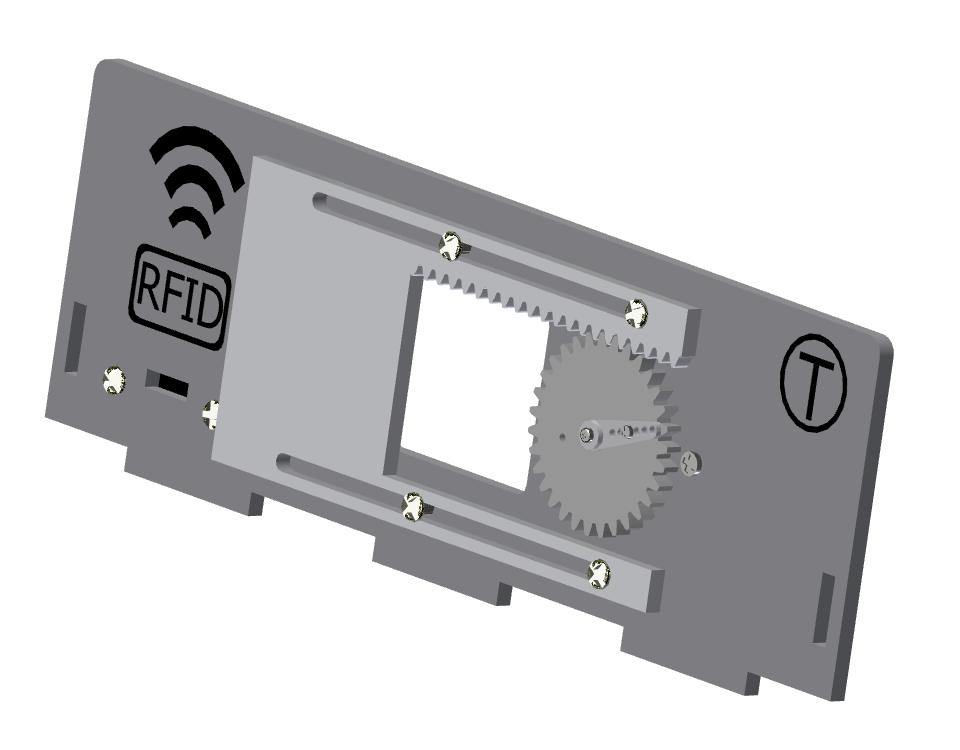
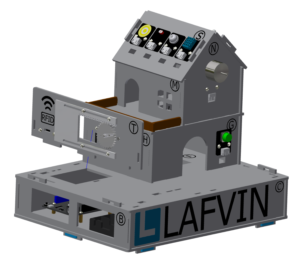
Steps 1-5: Install the gate to the garden
Parts List: Installed servos、 RFID sensor module、 and acrylic basswood board “T”.
The installation is shown in the following figure:
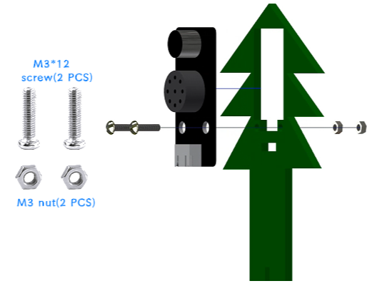
Step 2: Install the speech recognition module
Parts list: speech recognition module、 green basswood board、 M3*12mm screw (2 PCS)、 M3 nut (2 PCS).
The installation is shown in the following figure:
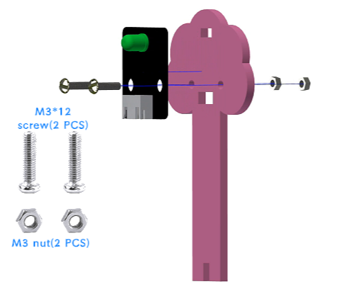
Step 3: Install of LED Light Module
Parts list: LED light module、 pink basswood board、 M3*12mm screw (2 PCS)、 M3 nut (2 PCS).
The installation is shown in the following figure:
Step 4: Install flowers and trees in the garden
Parts list: Green linden wood board with voice recognition module installed、 pink linden wood board with LED light module installed.
The installation is shown in the following figure:
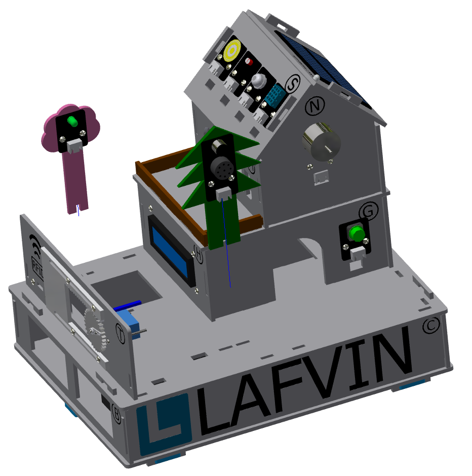
Step 5: Install the RGB Light Strip
Parts list: RGB light strip、 brown basswood fence board (The longest fence).
The installation is shown in the following figure:
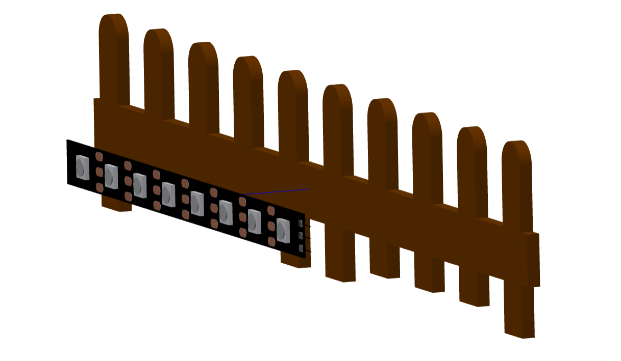
Precautions
First tear off the blue tape on the back of the light strip, and then stick the light strip on the back of the fence.
To achieve the best lighting effect, please stick the RGB light strip in the center of the back of the fence.
Step 6: Install of the Garden Fence
Parts list: Brown garden fence basswood planks (2 shorter ones)、 fence with RGB light strip installed.
The installation is shown in the following figure:
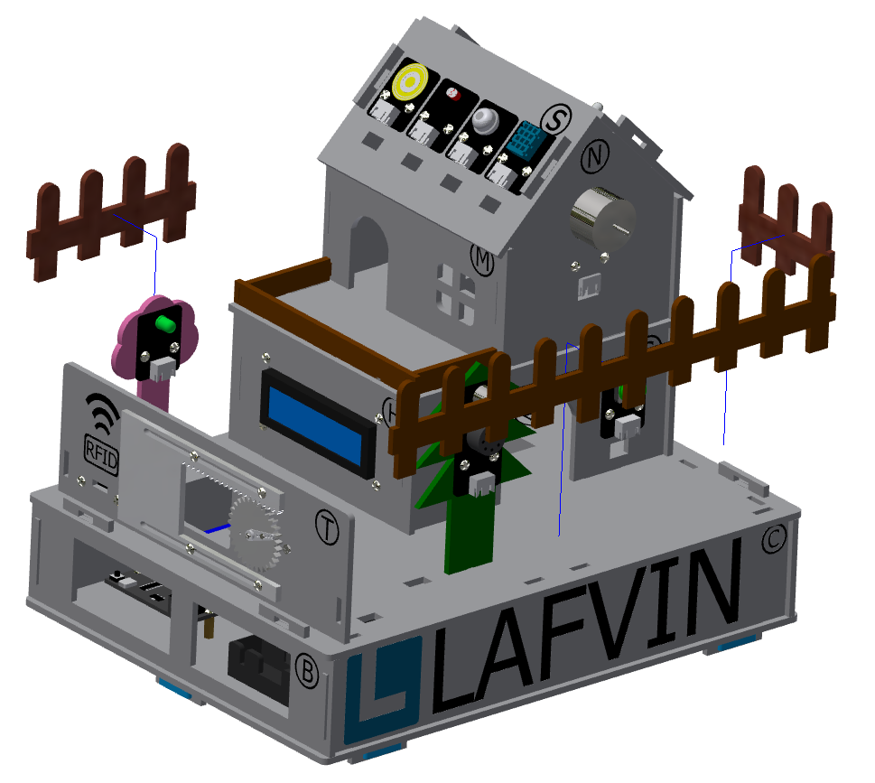
Precautions
Please distinguish between the short and long fences. The longer one should be installed next to the gate, and the shorter one should be installed next to the key module.
5.Installation of the fixed part of the cabin
Step 1: Attach the base
Parts List: Blue latch (8 PCS).
The installation is shown in the following figure:
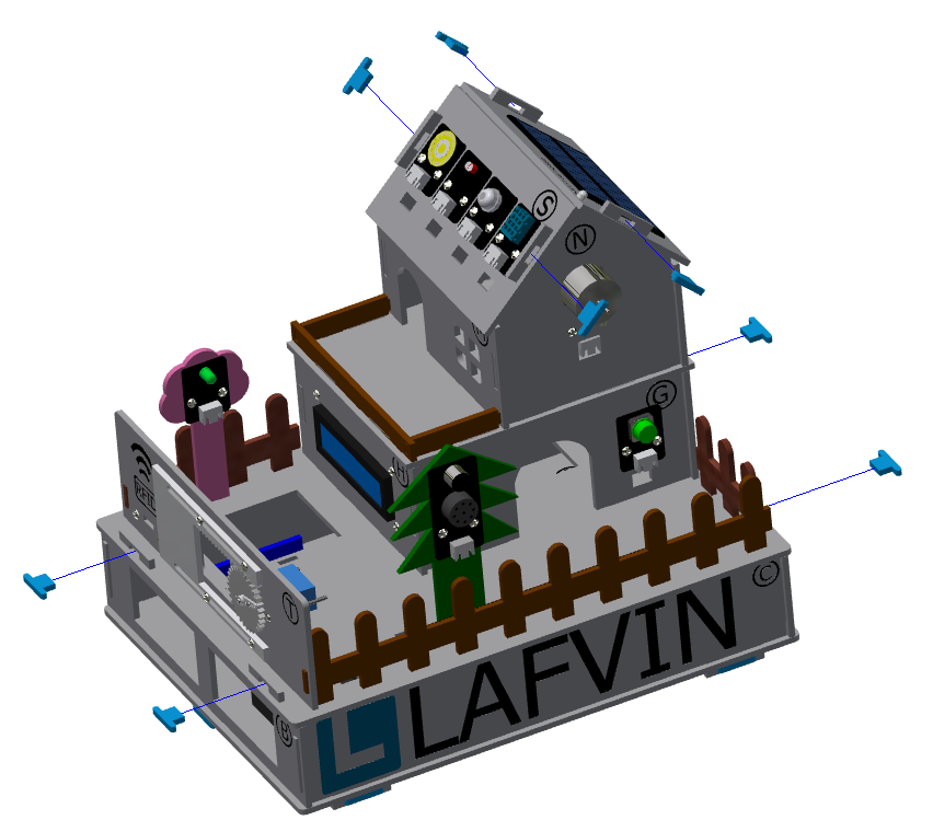
Precautions
Please install and tighten the latch after the sensor element is wired and debugged to ensure normal operation to ensure smooth installation and normal function.
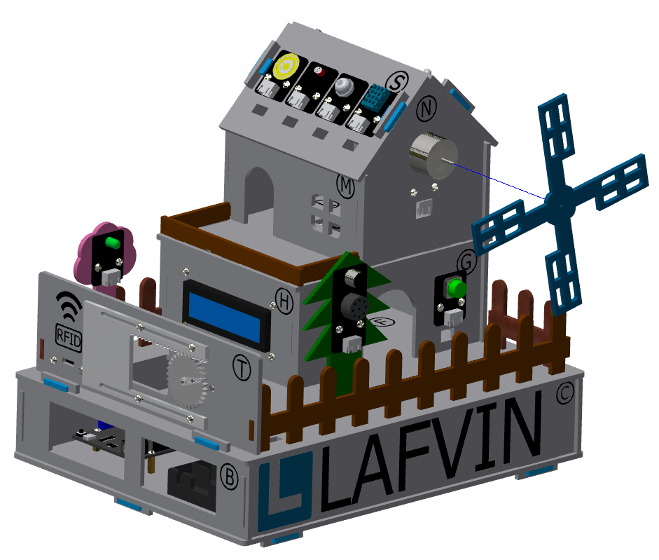
Step 2: Install the windmill blades
Parts List: Blue Windmill Blades.
The installation is shown in the following figure:
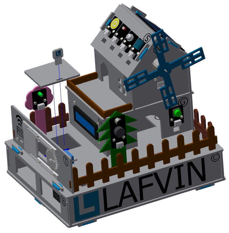
Step 3: Install the debug window cover
Parts list: debug window cover、 latch with logo.
The installation is shown in the following figure:
Precautions
This cover is convenient for daily device debugging, wiring inspection, and development board status inspection.